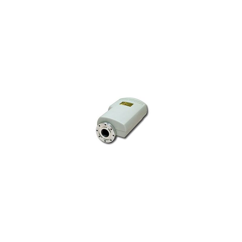
Invacom 0.3 dB Quad 4 outputs LNB universal C120
All professionals know the importance of the relationship between the signal and the figure of noise in an LNB, as a measure of the performance of a good LNB. Invacom presents its new range of Universal LNB'S C120.
- Read reviews
All professionals know the importance of the relationship between the signal and the figure of noise in an LNB, as a measure of the performance of a good LNB. Invacom presents its new range of Universal LNB'S:
C120 SINGLE (1 output)
C120 TWIN (2 outputs)
C120 QUATTRO (4 outputs / bands)
C120 QUAD (4 outputs)
The INVACOM LNB'S C120 with noise figure of 0.3 dB allow us to achieve a higher image and sound quality, even in the most compromised satellite installations. Its frequency of entrance in low band is of 10.7-11.7 GHz and in high band of 11.7-12.75 GHz. Its frequency of exit is of 950-2150 MHz and its gain, of 50-60 dB. The design of the LNB'S Invacom has been made with the latest 3D modeling software, which ensures the maximum transfer of energy from the satellite dish, to the electronics of the LNB. It is achieved thanks to the precise and optimal design of the housing and of the illuminator.
Invacom's LNB'S specifications are superior to those of other manufacturers, since its phase noise is 10 dB better. The cleaner the oscillator of an LNB, the greater its performance.
The positive gain of Invacom's LNBs compensates for long cable runs and helps prevent channel losses, due to harmonic distortions, in the receiver.
All Invacom LNB's are electrically and pressure tested twice, in several stages of their assembly. The finished units are tested again in extreme cold and hot temperatures, to ensure unparalleled operation.
Finally, each unit arrives to the customer with its own test of profit and figure of noise by frequency and the 4 bands, guaranteeing to the maximum the quality of the product.
Specifications
Range Frequencies Entry
-> Low Band 10.7 - 11.7 GHz
-> High Band 11.7 - 12.75 GHz
Range Frequencies Output
-> Low Band 950 - 2150 MHz
-> High Band 950 - 2150 MHz
Noise Figure dB 0.3
Gain dB 50 - 60
Local Oscillator Frequency
-> Low Band 9.75 GHz
-> High Band 10.6 GHz
Local Oscillator Phase Noise
-> 1 kHz -65 dBc / Hz
-> 10 kHz -95 dBc / Hz
-> 100 kHz -110 dBc / Hz
Local Oscillator Stability
-> Tip. = 1 MHz
-> Max. = 3 MHz
Consumption mA 200 (+30 per additional receiver)
Image rejection dB> 40
Cross Polarization Insulation dB> 30
Isolation between dB Bands> 30
Output Impedance Ω 75
Return Losses dB> 10
Range Tª Operation ºC -40 / +70
Difference Gain between Outputs dB <6
Control signals
-> Vertical High 11.5 V - 14 V & 22 kHz
-> Vertical Low 11.5 V - 14 V
-> Horizontal High 15.5 V - 19 V & 22 kHz
-> Horizontal Low 15.5 V - 19 V
Signal Frequency 22 kHz kHz 18 - 26
Time Transition Signal 22 kHz? S 5 - 15
Performance% 40 - 60
Impedance at 22 kHz Ω> 70
Waveguide interface? 18.5 mm, C-120
Summary
5
(1 Reviews)
Select a row below to filter reviews.


Anthony jackson
Excelente